Just like we did when adding a CPU to our project, PROFINET devices such as Interface Modules (IMs) can be added in a similar way through the Device & Networks view in TIA Portal.
Once the device is added to the project, the next steps are
- Assign the device to the PROFINET network
- Set a valid IP address, and
- Define the PROFINET Device Name.
After configuring the device in the project, we need to link it with the actual hardware. To do that
- Go to the Online Access tab
- Select the appropriate network interface card
- Click “Update accessible devices“ to scan the network
- And then assign the same IP address and device name as configured earlier in the Device & Networks section
This ensures that the TIA Portal can properly recognize and communicate with the physical PROFINET device on the network.


Adding Profinet Device
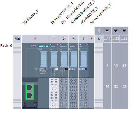
Adding Modules to the Interface Module (IM)
After adding the Interface Module (IM) to your project, you can start building your hardware configuration by adding I/O modules. This is done through the Hardware catalog, where you can choose from a variety of module types such as:
- DI (Digital Input)
- DO (Digital Output)
- AI (Analog Input)
- AO (Analog Output), and more.
Simply drag and drop the desired modules into the correct slots of the IM rack.
At the end of the module stack, make sure to add a Server Module — this is required to properly terminate the rack configuration and ensure communication with the PLC.
Also, pay attention to the base type of each module during configuration:
- Some modules require a black base
- Others require a white base.
Ensure these are correctly set according to the hardware specs.
Finally, by selecting each individual module in the configuration, you can assign symbolic names (PLC tags) to each I/O channel. This step helps with easier identification and usage of signals within your program.


Adding Modules
Configuring AI / AO Modules
Once you have added your AI / AO modules to the IM rack, you must configure each channel’s measurement properties. For each analog channel:
- Set the Measurement Type (Voltage or Current).
- Select the appropriate Measuring Range
In TIA Portal, this is done via the module’s Properties under General → Channel Parameters (or Measuring).
If the module supports measuring range adjustment, you can further narrow the span by providing a custom lower and upper limit (in mV or µA) to improve resolution within a sub‑range.
After setting the measurement type and range, switch to the I/O Tags pane to assign a symbolic name (PLC tag) for each channel. This tag will correspond to the raw value (integer) of the analog input and will be used in your user program.



Configuring Modules
Compile, Rebuild and Download
Once all your hardware configuration is complete (including modules, IPs, PROFINET names, and tags), the final steps are:
- Perform a hardware compile / rebuild all to ensure that the entire device and module configuration is validated and consistent.
- Then do a download (to device) so that the configuration actually gets transferred to the physical CPU and modules.
By doing Compile → Hardware (Rebuild All) and then Download you ensure that TIA Portal checks for errors and synchronizes your offline project with the online device.


Compile Hardware and Download
If you found this helpful, please consider supporting with a small donation. Thank you!
Leave a Reply