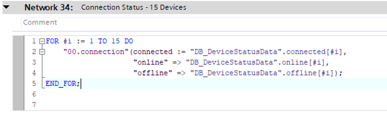
As automation projects scale in size and complexity, the need for consistency, maintainability, and reusability becomes increasingly important. In this chapter, we introduce the concept of libraries in TIA Portal and explain how they can be used to organize, reuse, and share code components across multiple projects or within a team.
Libraries allow engineers to encapsulate frequently used logic—such as motor control, signal handling, or data processing—into Function Blocks (FBs), Functions (FCs), and Data Types (UDTs) that can be saved, versioned, and imported into other projects. This promotes standardization and reduces development time, especially in environments where multiple machines or systems share similar control structures
We also explore how to use Siemens-compatible external libraries, such as the LGF (Library for General Functions), and integrate them into real-world applications. These libraries often include powerful utility blocks (e.g., for interpolation, diagnostics, math operations) that can accelerate development and improve code quality
Furthermore, next chapter covers best practices for writing reusable blocks, including how to design generic, parameterized logic using structured data types, and how to manage library versions to avoid compatibility issues in long-term projects.
To make the function block more reusable and resilient to changes in the size of the button array, the fixed indexing (1 TO 10) can be replaced with dynamic bounds using the built-in LOWER_BOUND and UPPER_BOUND functions.
Instead of hardcoding the array size in the FB interface like this:
buttons : IN_OUT ARRAY[1..10] OF button
the array is declared as open-ended:
Open-ended Array
This allows the same FB to operate on arrays of any size, determined at the call location.
Inside the loop, we use the following logic:
Use of Lower_Bound & Upper_Bound on an open-ended array
Benefits of This Approach
Flexibility: The function block can be reused with arrays of any length, without modification.
Safety: Using LOWER_BOUND and UPPER_BOUND protects the CPU from potential runtime errors caused by index out-of-range issues.
Scalability: If the system expands from 10 to 50 buttons, only the data block needs to be updated — no changes are required in the FB code.
This technique aligns with modern structured programming principles and is especially useful in large-scale or dynamic systems where component counts may vary.
If you found this helpful, please consider supporting with a small donation. Thank you!
As PLC projects grow in complexity, organizing data becomes critical for both readability and maintainability. Using individual variables quickly becomes inefficient and error-prone, especially when dealing with repeated structures such as sensor arrays, motor configurations, or control parameters. This is where User-Defined Data Types (UDTs) come into play.
UDTs allow engineers to define their own structured data types that group multiple related variables under a single object. These structures can then be reused throughout a project, dramatically improving consistency, reducing code duplication, and simplifying troubleshooting
This chapter introduces the concept of structured data in the TIA Portal and explains how to create and implement UDTs in real-world automation projects. You’ll learn how to design logical, scalable data structures and use them effectively inside data blocks and function blocks.
Objectives
By the end of this chapter, you will be able to:
Understand the concept and purpose of structured data and UDTs in PLC programming.
Create custom data types (UDTs) in TIA Portal for common industrial use cases.
Implement UDTs within global and instance data blocks (DBs).
Use arrays of UDTs to manage large sets of related components (e.g., sensors, actuators).
Apply best practices for naming, organizing, and documenting structured data.
Why UDTs Are Important
Using UDTs introduces several advantages into your PLC project architecture:
Consistency: All devices or components that share the same data structure can be initialized and handled in a uniform way.
Reusability: A single UDT definition can be reused across many blocks or functions, reducing programming time.
Scalability: Adding more components (e.g., 50 temperature sensors) becomes a matter of extending an array, not duplicating logic.
Maintainability: Well-structured data is easier to troubleshoot, monitor, and modify over time.
Clarity: Your code becomes more readable for both yourself and other engineers who may work on the project in the future.
When to Use UDTs
UDTs are particularly useful in the following scenarios:
Grouping sensor or actuator data (e.g., status, value, diagnostics).
Creating configuration profiles for devices such as motors, valves, or pumps.
Defining control parameters (e.g., setpoints, limits, gains) for PID or motion logic.
Structuring communication data with external systems or PCBs.
Practical Example: Handling an Array of Buttons Using a UDT and IN_OUT
To demonstrate the benefits of structured data and reusable logic, let’s consider a typical scenario in automation systems — managing a set of input buttons and their corresponding feedback.
Creating the UDT
A UDT named button is defined with two substructures:
Creating New PLC Data Type
command: Contains control signals such as .enable (Bool)
feedback: Contains status signals such as .enabled (Bool)
This structure allows a clean separation between control inputs and feedback outputs for each button.
Structure of a PLC Data TypePicture 3: Use this Data Type to create an array of buttons
Creating an Array of Buttons
In a global data block, an array of 10 buttons is created:
This models a panel or interface with 10 independent buttons, each having its own command and feedback data
Array of UDT on a Global Data Block
Function Block with IN_OUT Parameter
A function block (FB) is created with the following interface:
Using IN_OUT allows the function block to read and modify the original data in the calling block, maintaining data integrity across the project without needing intermediate variables or return values.
Implementation Logic
Inside the function block, a FOR loop is used to iterate through all 10 buttons. For each one, the code checks whether the command.enable flag is set. If it is, the feedback.enabled is set to true. Otherwise, it is set to false.
FB – UDT as inOut variable
Call the FB on OB and map the buttons of Data block to the input of FB
This simple loop-based logic demonstrates several key programming practices:
How to efficiently iterate over structured data using loops
How to use IN_OUT parameters to directly interact with DB data
How structured design improves readability and modularity
Why This Matters
Without using UDTs and arrays, the same logic would require 10 individual IF statements, each targeting separate variables. This not only increases code size but also leads to duplication and higher risk of errors.
By combining UDTs, arrays, and structured access, the code becomes significantly more scalable, clean, and easy to maintain — especially when the number of elements increases or the logic becomes more complex.
If you found this helpful, please consider supporting with a small donation. Thank you!
When working with Siemens automation projects in the TIA Portal, it’s not always necessary to have a physical PLC on hand. Thanks to S7-PLCSIM, Siemens’ virtual PLC simulator, you can fully test your logic, monitor tags, and validate system behavior before deploying to actual hardware. This guide walks you through the steps to simulate your project using S7-PLCSIM, from setup to going online with your virtual CPU.
Step-by-Step Guide to Simulating Your Project in TIA Portal with S7-PLCSIM:
Install S7-PLCSIM on your computer
Before starting, make sure that S7-PLCSIM is installed. This is a separate Siemens software package that allows you to simulate an S7-1200 or S7-1500 CPU.
Open your TIA Portal project
Launch TIA Portal and open the project you want to simulate.
Click the Simulation button
In the toolbar, click the simulation icon (it usually looks like a small CPU or has the label “Start Simulation”). This will open the PLCSIM environment.
Download configuration window appears
Once simulation is activated, the download dialog will open. In the PG/PC Interface section, make sure that “PLCSIM” is selected (it should be the default when PLCSIM is running).
The software will search for available CPUs
TIA Portal will scan and detect the virtual CPU, often using a default IP like 192.168.25.1.
Certification warning may appear
If prompted with a message about associated certification, simply click Connect to proceed.
Click “Load” to download the program
Once the virtual CPU is detected, click the Load button to transfer your project to PLCSIM.
Start the CPU module
After loading, either click Start Module directly from the download window or start the CPU manually from within the PLCSIM interface.
Final Step: Go Online
After the download and startup are complete, you can go online with the simulated CPU just like you would with a real one. This allows you to monitor variables, force inputs/outputs, and test your logic in a fully virtual environment.
Open Project And Click The Simulation Button
Simulation will automatically Start (PLCSIM v19)
Return To project and Load The propject
Certification warning may appear
Click Load to Download The Project
Select Start Module ( or start the CPU after download completed)
Go Online using PLCSIM
If you found this helpful, please consider supporting with a small donation. Thank you!
In this chapter, we demonstrate how to implement P2P (Point-to-Point) communication using Siemensfunction blocks in TIA Portal, with a focus on handling serial communication with a CHAR buffer. We’ll present two basic examples:
Receive-Only with Buffer Reset
Send-Only Example
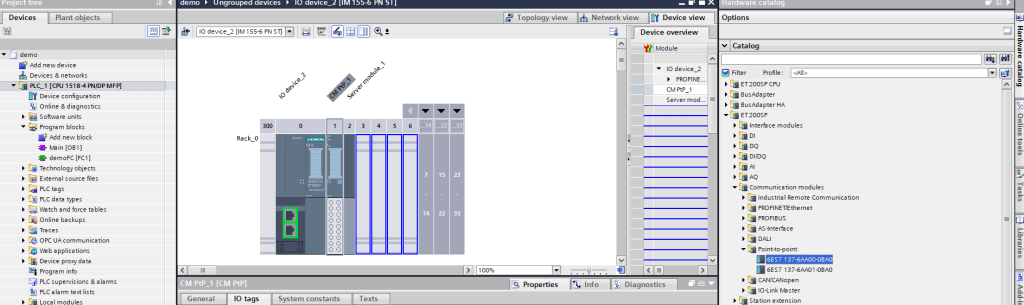
Hardware Configuration
Insert CM p2p module
Modify interface settings / RS232 – 9600 – 8N1
Example 1: Receive-Only with Timeout and Buffer
Clear Goal:
Receive data through the serial port into a CHAR buffer.
If no new data is received for 3 seconds, clear the buffer.
Use Receive_Reset_P2P to reset the P2P block after buffer clear
Use variables and Logic as shown in picture
Receive Logic Variables
Receive Logic
Notes
FILL_BLK is a fast and efficient way to reset a buffer of CHAR or BYTE data.
Use TON to detect a lack of new data (NDR = FALSE) over time.
You can visualize receiveBuffer in the watch table or monitor it in runtime.
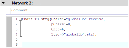
Use Chars_To_Strg to convert an array of characters to string
Example 2: Send-Only Using Send_P2P (with 1Hz trigger) Goal:
Send data via serial communication (P2P) at a fixed interval (1Hz), using a predefined array of bytes. The data length is fixed for simplicity, although in your actual application it may vary dynamically.
Variables Declariation
Logic Description
The block Send_P2P is triggered once per second (1Hz).
The transmission happens only if transmitEnable is TRUE.
The REQ input of Send_P2P uses a positive edge from the 1Hz clock (using TON timer or clock bit).
The data length is fixed (e.g., 50 bytes), but can be dynamic in your implementation.
Transmit Logic
Notes
transmitBuffer should be filled with valid data before sending. For example, in your real project, you might build a message dynamically before each transmission.
BUFFER_LEN is fixed here for simplicity (e.g., 50), but can be made dynamic depending on message content length.
PortTx should match the hardware port from the device configuration in TIA Portal.
The send trigger is periodic (1Hz), and gated with transmitEnable, using a standard contact (NO).
If you found this helpful, please consider supporting with a small donation. Thank you!
Welcome to the final chapter of our TIA Portal Tutorial series, where we dive into advanced concepts and practical techniques to elevate your PLC programming skills. In this section, we will explore powerful features such as User-Defined Data Types (UDTs), reusable Function Blocks, and efficient code organization through Libraries. You’ll also learn how to leverage Siemens’ RecipeImport_DB and RecipeExport_DB blocks for structured recipe management, integrate external libraries and Library Global Functions (LGFs), and implement robust PID control using the PID_Compact block.
Whether you’re aiming to build scalable, maintainable automation projects or optimize process control, this chapter will provide you with the essential tools and know-how to take your TIA Portal projects to the next level. Let’s get started!
In this chapter, we will explore the three basic timer types used in TIA Portal programming: TON (On-Delay Timer), TOF (Off-Delay Timer), and TP (Pulse Timer). We will provide practical examples demonstrating their typical applications.
TON – On-Delay Timer
Function
Delays the activation of an output by a specified time after the input signal turns TRUE.
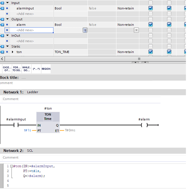
Example 1: Activate an Alarm 1 Second After Signal Arrival
Objective: When the input signal becomes TRUE, the alarm output will turn ON after a 1-second delay.
SCL / Ladder Implementation
Create a new Function Block (FB) and prepare the structure. Use Ladder or SCL, not both
Call the FB to OB1 and map Input and Output
TOF – Off-Delay Timer
Function
Keeps the output ON for a specified time after the input signal turns FALSE.
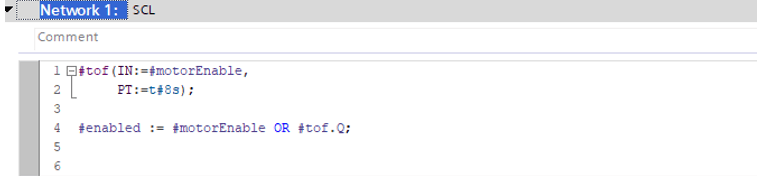
Example 2: Keep Motor ON if Input is Lost for Less Than 1 Second
Objective: Motor stays ON while the input signal is TRUE. If the input drops FALSE, the motor remains ON for 1 second before turning OFF.
SCL / Ladder Implementation
Create a new Function Block (FB) and prepare the structure
Call the FB to OB1 and map Input and Output
TP – Pulse Timer
Function
Generates a fixed-length pulse on the output when the input signal goes TRUE.
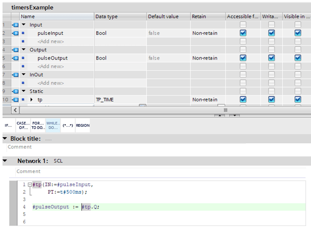
Example 3: Generate a 500 ms Pulse When Input is Activated
Objective: When the input signal changes from FALSE to TRUE, output a 500 ms pulse.
SCL / Ladder Implementation
Create a new Function Block (FB) and prepare the structure
Call the FB to OB1 and map Input and Output.
Summury
Timer
Description
Typical Use Case
TON
Delays output ON after input TRUE
Delay alarms, soft start signals
TOF
Delays output OFF after input FALSE
Motor run-on timers, signal hold
TP
Generates fixed-length pulse
Pulse outputs, triggers, alarms
If you found this helpful, please consider supporting with a small donation. Thank you!
This chapter presents two real-world examples using Functions (FC) in TIA Portal to demonstrate basic logic handling and analog value scaling using SCL.
In the first example, we use a BOOL input to set two status outputs.
In the second example, we process an analog signal using NormX and ScaleX instructions, with additional logic for alarm thresholds.
Example 1 – Digital Input to Online/Ofline Status
Objective
Create an FC that:
Accepts a BOOL input (e.g. a connection status).
Outputs two BOOL signals: Online and Ofline.
Logic
If the input is TRUE, Online := TRUE and Ofline := FALSE.
If the input is FALSE, Online := FALSE and Ofline := TRUE.
Block: FC_DeviceStatus
Interface
Name
Type
Data Type
Connected
IN
BOOL
Online
OUT
BOOL
Offline
OUT
BOOL
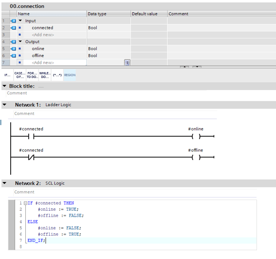
Logic (SCL or Ladder):
Example Implementation – Choose One Method SCL or Ladder, not Both
Call FC to OB1 (drag and Drop) – Set PLC tags from Input and Output
Input = False, Online= False, Ofline = True
Input = True, Online= True, Ofline = False
Example 2 – Analog Scaling with Alarm Levels
Objective
Create an FC that:
Takes an INT input representing a raw analog value (e.g., from 4–20 mA input).
Uses NormX and ScaleX to convert the raw signal into a scaled value (0–100).
Sets:
Alarm := TRUE if the scaled value is less than 20
Warn := TRUE if the scaled value is between 21 and 30
Block: FC_AnalogMonitor
Interface
Name
Type
Data Type
RawInput
IN
INT
ScaledValue
OUT
REAL
Alarm
OUT
BOOL
Warn
OUT
BOOL
normVal
Temp
REAL
Logic (SCL):
Example Implementation
Summary
FC
Purpose
Key Concepts USed
FC_DeviceStatus I
Basic digital logic
F, BOOL output control
FC_AnalogMonitor
Analog scaling + alarm thresholds
NormX, ScaleX, IF, REAL math
These examples demonstrate the power and flexibility of using Functions (FC) with SCL to encapsulate
These examples demonstrate the power and flexibility of using Functions (FC) with SCL to encapsulate.
Status Healthy
Warn Present
Alarm Present
If you found this helpful, please consider supporting with a small donation. Thank you!