• PLC Steps

    Simplify, Learn, Automate

    Γνῶσις δύναμις ἐστίν

    TIA Portalsupports multiple programming languages for implementing PLC logic. Each block (OB, FC, FB) can be developed in one of the following formats:

    • Ladder Diagram (LAD)
      • Graphical, logic-based language resembling electrical relay logic.
      • Widely used in industrial automation due to its visual clarity.
      • Ideal for simple logic, digital I/Os, and maintenance-friendly programming.
    • Structured Control Language (SCL)
      • Text-based language similar to Pascal or high-level programming languages.
      • Supportsstructured programming: IF, FOR, CASE, mathematical expressions, etc.
      • Bestsuited for complex algorithms, scaling, string manipulation, and loops.
    • Statement List (STL)
      • Low-level, mnemonic-based language.
      • Representslogic as assembly-like instructions.
      • Rarely used in modern projects — mostly for legacy systems or low-level debugging.

    Example: Simple NO / NC Contact Assignment

    Let’s look at the same logic written in both LAD and SCL.

    Objective:

    If a normally open (NO) input is TRUE, turn on an output coil.

    Simple NO Contact Assignemt

    Notes:

    • In LAD, logic is built by connecting graphical elements.
    • In SCL, logic is written with structured code and requires strictsyntax (e.g., semicolons).
    • Both formats are compiled to the same machine code and executed by the PLC identically.

    Structured Control Language (SCL) Basics

    Structured Control Language (SCL) is a high-level, text-based programming language used in TIA Portal for developing logic in PLC blocks (OB, FC, FB). It is based on the IEC 61131-3 standard and is very similar to languages like Pascal or ST (Structured Text)

    SCL is highly readable, modular, and especially powerful for arithmetic operations, conditional logic, loops, and working with complex data structures

    Syntax Basics

    • Every instruction ends with a semicolon (;)
    • Blocks of logic are enclosed within structured keywords like IF…THEN…END_IF, FOR…DO…END_FOR,etc
    • Assignments use the := operator.

    Common Opertors

    OpearatorDescriptionExample
    :=AssignmentA := B + 5;
    +-*/ArithmeticSpeed := A * 2;
    ANDLogical ANDA AND B
    ORLogical ORA OR B
    NOTLogical NOTNOT A
    =Equality checkIF A = B THEN
    <>Not equalIF A <> B THEN
    <,>,<=,>=ComparisonIF A > 10 THEN

    Example

    Motor_ON := Start_Button;

    This assignsthe value of Start_Button (BOOL) to the variable Motor_ON

    IF / THEN / ELSE

    The IF structure allows conditional execution of code.

    IF Sensor_Value > 100 THEN

    Alarm := TRUE;

    ELSE

    Alarm := FALSE;

    END_IF;

    You can also use ELSIF for multiple conditions:

    IF Temp < 10 THEN

    Status := 1;

    ELSIF Temp < 20 THEN

    Status:= 2;

    ELSE

    Status:= 3;

    END_IF;

    FOR Loop

    The FOR loop is used to iterate a block of code a specific number of times.

    FOR i := 1 TO 10 DO

    Sum := Sum + Values[i];

    END_FOR;

    Arrays must be properly indexed and declared. Example:

    Values : ARRAY[1..10] OF INT;

    CASE Statement

    Alternative to multiple IF-ELSIF conditions.

    CASE Mode OF

    1: Motor_Speed := 100;

    2: Motor_Speed := 200;

    3: Motor_Speed := 300;

    ELSE

    Motor_Speed := 0;

    END_CASE;

    Commentsin SCL

    • Single-line comment:
      • // This is a comment
    • Multi-line comment:

    (* This is a

    multi-line comment *)

    Practical Example – Basic Control Logi

    // Start motor if Start button is pressed and no fault

    IF Start_Button AND NOT Fault THEN

    Motor := TRUE;

    ELSE

    Motor := FALSE;

    END_IF;

    Best Practices

    • Use meaningful variable names (e.g. Pump_Start instead of P1).
    • Always initialize variables in startup logic or OB100.
    • Prefer IF or CASE for readability over nested logic.
    • Use FOR loops only with known boundsto avoid infinite loops.

    Summary

    SCL provides a powerful and clean way to write structured, readable PLC code, especially useful for:

    • Complex calculations
    • Conditional logic
    • Loops and array handling
    • Scalable, modular logic design

    If you found this helpful, please consider supporting with a small donation. Thank you!

  • PLC Steps

    Simplify, Learn, Automate

    Γνῶσις δύναμις ἐστίν

    In this chapter, we move beyond hardware setup and dive into the heart of PLC development: programming.

    You’ll get introduced to the most widely used programming languages in the Siemens TIA Portal environment, such as Ladder Diagram (LD) and Structured Control Language (SCL). We’ll explore how to write clean and reusable code using Functions (FCs), and how to apply tools like ScaleX and NormX for signal scaling.

    You’ll also learn how to work with loops (FOR) to call logic repeatedly, how to manage timing using timers (TON, TOF, TP), and how to detect signal edges with R_TRIG and F_TRIG.

    By the end of this chapter, you’ll have a strong foundation for writing scalable, efficient, and structured logic in your PLC programs — moving from simple operations to more advanced control strategies.


    Chapters

  • PLC Steps

    Simplify, Learn, Automate

    Γνῶσις δύναμις ἐστίν

    Common Data Types in TIA Portal

    TIA Portalsupports a wide variety of data types used to represent values, signals, states, timers, characters, and structured data. Below are the most frequently used types when programming OBs, FCs, FBs, and DBs.

    BOOL

    • Represents a binary value: TRUE or FALSE.
    • Typically used for digitalsignals, flags, and conditions.

    INT / UINT

    • INT: 16-bit signed integer → Range: -32,768 to +32,767
    • UINT: 16-bit unsigned integer → Range: 0 to 65,535
    • Used for counters, timers, small numeric values.

    DINT / UDINT

    • DINT: 32-bit signed integer → Range: -2,147,483,648 to +2,147,483,647
    • UDINT: 32-bit unsigned → Range: 0 to 4,294,967,295
    • Used when larger numerical range is needed (e.g., encoder values, runtime logs).

    REAL / LREAL

    • REAL: 32-bit floating point number (approx. 7 decimal digits precision)
    • LREAL: 64-bit floating point number (higher precision, approx. 15-17 digits)
    • Used for analog signals, scaling, calculations with decimals.

    BYTE

    • 8-bit data type. Can be used for grouping 8 BOOLs or storing raw values.
    • Often used for communication buffers or binary flags.

    CHAR

    • Stores a single ASCII character (1 byte).

    STRING / WSTRING

    • STRING: A series of ASCII characters (up to 254 characters).
    • WSTRING: Wide-character string (for Unicode/UTF-16 support), typically used in multilingual or HMI applications.

    TIME

    • Stores time values (e.g., T#5s, T#1h30m10s).
    • Used for timers, delays, or timestamping.

    ARRAY [x..y] OF <type>

    • Collection of elements of the same type, indexed by position.
    • Example: ARRAY [1..5] OF INT stores 5 integer values.
    • Commonly used for sensor arrays, batch data, or buffer management.

    Variable Interface Types(Declaration Sections)

    Each block type (FC, FB, OB) in TIA Portal allows you to declare variables in different interface sections, each serving a specific purpose in terms of data flow and memory usage.

    Input (IN)

    • Read-only from inside the block.
    • Values are passed from the calling block to the function or function block.
    • Cannot be modified inside the block.

    Example: A temperature setpoint passed into a heating control FB.

    Output (OUT)

    • Write-only from inside the block.
    • Used to send data back to the caller.
    • Must be assigned a value within the block to be meaningful.

    Example: An error flag that indicates fault status to the calling OB.

    InOut

    • Allows the block to both read and modify the same variable.
    • Changes are reflected back to the caller.
    • Used with caution — potential for unexpected side effects.

    Example: A cumulative runtime counter that is updated in each scan.

    Temp

    • Temporary variables, stored in the local stack of the block.
    • Exist only during block execution and are not retained.
    • Cannot be accessed outside the block.
    • Ideal for intermediate calculations orstate tracking that doesn’t need to persist.

    Example: A temporary result in a math formula inside an FC.

    Summary Table

    Data TypeDescriptionTypical Use
    BOOLTRUE / FALSEDigital I/O, flags
    INT , DINTSigned integersCounters, value
    REAL , LREALFloating pointAnalog values, scaling
    BYTE8 bitsGrouped bits, comms
    CHAR ,STRING, WSTRINGText dataHMI, logging
    TIME Time formatTimers, delays
    ARRAY [x,y] OF …Indexed listBuffers,sensor groups
    Variable TypeDirectionScopePersistence
    InputINFrom caller → blockRead-only
    OutputOUTFrom block → callerWrite-only
    InOutBothSharedRead/Write
    TempInternalLocal OnlyLost after execution

    Example of Variables Declaration


    If you found this helpful, please consider supporting with a small donation. Thank you!

  • PLC Steps

    Simplify, Learn, Automate

    Γνῶσις δύναμις ἐστίν

    Introduction

    In TIA Portal, a PLC program is structured into modular componentsthat help organize logic, improve code reusability, and manage memory efficiently. The most fundamental elements include:

    • Organization Blocks (OBs) – Define when and how code is executed by the CPU.
    • Functions (FCs) – Reusable code blocks without memory retention.
    • Function Blocks (FBs) – Reusable code blocks with memory retention.
    • Data Blocks (DBs) – Hold data used by FBs or shared globally.

    Organization Blocks (OBs)

    Organization Blocks are the entry points for code execution. They are called by the operating system of the CPU and are executed according to predefined events or triggers (e.g. cyclic, startup, error, or time-based)

    OB1 – Main Program Cycle

    • Type: Cyclic OB
    • Purpose: This is the main loop of the PLC program. It is executed continuously and cyclically as long as the CPU is in RUN mode
    • Typical Use: General logic execution, calling FCs/FBs, reading inputs, writing outputs.
    • Execution: After OB1 finishes executing, itstarts again immediately, creating the main PLC scan cycle.

    OB100 – Startup OB

    • Type: Startup OB
    • Purpose: Executed once when the CPU transitionsfrom STOP to RUN.
    • Typical Use: Initialization of variables, flags, timers, and starting conditions.
    • Important Note: OB100 is not called on a cold restart unless explicitly configured. It is typically used to reset statuses or force certain startup values

    OB35 – Cyclic Interrupt OB

    • Type: Time-triggered (cyclic interrupt) OB
    • Purpose: Executes at fixed time intervals, independently of the main OB1 cycle.
    • Typical Use: Time-critical or synchronized tasks(e.g. reading fast analog signals, updating motion control values)
    • Configuration: The execution interval (e.g., every 100ms) is set in the hardware configuration.

    Tip: Since OB35 runs asynchronously to OB1, be careful when accessing shared variables — consider using consistent access or shared data blocks with appropriate data handling to avoid conflicts.

    Functions(FC)

    • No Memory Retention: FCs do not retain data between calls unless explicitly passed through parameters
    • Usage: Bestsuited for general-purpose tasks like calculations, logic checks, conversions.
    • Structure: Accept input, output, and in/out parameters, but have no associated data block.

    Example: An FC can calculate the average of 3 sensor readings and return the result.

    Function Blocks(FB)

    • With Memory Retention: FBs maintain internal state using an Instance Data Block.
    • Usage: Ideal for objects or devices that need to remember internal status — e.g. motor control, pump logic, debouncing, PID control.
    • Structure: Also usesinput, output, and in/out parameters, plus internal static variables.

    Example: An FB controlling a motor may retain the motor’s running state, error codes, or runtime counters.

    Data Blocks (DB)

    There are two main types

    1. Instance Data Blocks
      • Automatically generated and linked to FBs.
      • Store the internal data of a specific FB instance.
    2. Global Data Blocks
      • Independent DBs accessible from any part of the program.
      • Used to store shared configuration data, setpoints,statuses, flags, etc.

    Best Practice: Avoid writing to global DBs from multiple sources unless coordinated — this reduces the chance of race conditions or inconsistent data.

    Summary

    Block TypeRetains MemoryTriggered ByPurpose
    OB1N/ACPU cyclic scanMain logic execution
    OB100N/ACPU startupInitialization
    OB35N/ATime interruptTime-based logic
    FCCalled manuallyStatelessreusable logic
    FBYes (via DB)Called manuallyStateful logic with memory
    DBYesAccessed by logicData storage

    Differente Types Of Blocks

    Important Note: Calling Logic from OBs

    In TIA Portal, the PLC only executes code that is explicitly called from an OB (Organization Block).

    Creating an FC or FB does not automatically make it run. You must call it manually from an OB (typically OB1 or OB35), or from within another block that is already being executed.

    Example

    If you create an FB named FB_MotorControl and define all your motor logic inside it, nothing will happen unless you add a call to FB_MotorControl (with its instance DB) inside OB1 or another OB.

    Wrong Assumption

    “Since I wrote the code inside FB, the PLC will run it automatically.”

    No – it will be ignored unless called. Best

    Practice

    • Use OB1 to structure your main logic and call all necessary FCs/FBs from there.
    • For more modularity, you can group logic in multiple FCs/FBs and manage execution order inside OB1.
    • For time-critical logic, consider calling blocksfrom OB35 or other cyclic interrupt OBs.

    Understanding FB Calls and Automatic Data Block Creation

    When you call an FB from an OB (e.g., OB1) for the first time, TIA Portal will automatically prompt you to create an Instance Data Block (DB). This DB is used to store the internal memory of the FB, such as variables, statuses, timers, counters, or any static data defined within the FB.

    Note: If you don’t create the associated DB, the FB cannot be compiled or executed — because it has
    nowhere to store its state

    Multiple Instances:

    If you want to control multiple motors using the same FB (e.g., FB_MotorControl), you can call the same FB multiple times but with different instance DBs

    Summary Point to Add

    • FBs always require a corresponding instance DB when called.
    • TIA Portal automatically manages this and will prompt you to create one on first use.
    • You can have multiple instances of the same FB, each with its own DB.

    If you found this helpful, please consider supporting with a small donation. Thank you!

  • PLC Steps

    Simplify, Learn, Automate

    Γνῶσις δύναμις ἐστίν

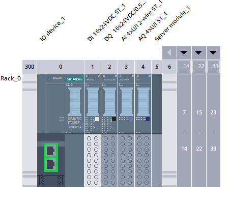
    Just like we did when adding a CPU to our project, PROFINET devices such as Interface Modules (IMs) can be added in a similar way through the Device & Networks view in TIA Portal.

    Once the device is added to the project, the next steps are

    1. Assign the device to the PROFINET network
    2. Set a valid IP address, and
    3. Define the PROFINET Device Name.

    After configuring the device in the project, we need to link it with the actual hardware. To do that

    1. Go to the Online Access tab
    2. Select the appropriate network interface card
    3. Click Update accessible devices to scan the network
    4. And then assign the same IP address and device name as configured earlier in the Device & Networks section

    This ensures that the TIA Portal can properly recognize and communicate with the physical PROFINET device on the network.

    Adding Profinet Device

    Adding Modules to the Interface Module (IM)

    After adding the Interface Module (IM) to your project, you can start building your hardware configuration by adding I/O modules. This is done through the Hardware catalog, where you can choose from a variety of module types such as:

    • DI (Digital Input)
    • DO (Digital Output)
    • AI (Analog Input)
    • AO (Analog Output), and more.

    Simply drag and drop the desired modules into the correct slots of the IM rack.

    At the end of the module stack, make sure to add a Server Module — this is required to properly terminate the rack configuration and ensure communication with the PLC.


    Also, pay attention to the base type of each module during configuration:

    • Some modules require a black base
    • Others require a white base.

    Ensure these are correctly set according to the hardware specs.

    Finally, by selecting each individual module in the configuration, you can assign symbolic names (PLC tags) to each I/O channel. This step helps with easier identification and usage of signals within your program.

    Adding Modules

    Configuring AI / AO Modules
    Once you have added your AI / AO modules to the IM rack, you must configure each channel’s measurement properties. For each analog channel:

    • Set the Measurement Type (Voltage or Current).
    • Select the appropriate Measuring Range

    In TIA Portal, this is done via the module’s Properties under General → Channel Parameters (or Measuring).

    If the module supports measuring range adjustment, you can further narrow the span by providing a custom lower and upper limit (in mV or µA) to improve resolution within a sub‑range.

    After setting the measurement type and range, switch to the I/O Tags pane to assign a symbolic name (PLC tag) for each channel. This tag will correspond to the raw value (integer) of the analog input and will be used in your user program.

    Configuring Modules

    Compile, Rebuild and Download

    Once all your hardware configuration is complete (including modules, IPs, PROFINET names, and tags), the final steps are:

    • Perform a hardware compile / rebuild all to ensure that the entire device and module configuration is validated and consistent.
    • Then do a download (to device) so that the configuration actually gets transferred to the physical CPU and modules.

    By doing Compile → Hardware (Rebuild All) and then Download you ensure that TIA Portal checks for errors and synchronizes your offline project with the online device.

    Compile Hardware and Download


    If you found this helpful, please consider supporting with a small donation. Thank you!

  • PLC Steps

    Simplify, Learn, Automate

    Γνῶσις δύναμις ἐστίν

    In industrial automation and control systems, signals are used to transmit information between sensors, controllers, and actuators. These signals can be either analog or digital, and understanding their characteristics is essential for designing, troubleshooting, and maintaining reliable industrial processes.

  • PLC Steps

    Simplify, Learn, Automate

    Γνῶσις δύναμις ἐστίν

    TCP / IP & Profinet

    Welcome to the TCP/IP & PROFINET section of our blog. Here, we dive into two of the most fundamental and widely used communication protocols in the world of industrial automation.

    TCP/IP forms the backbone of modern networking — from office systems to industrial environments — enabling structured, reliable, and scalable data exchange. It’s the foundation upon which most contemporary communication networks are built.

    PROFINET, on the other hand, is a specialized industrial Ethernet protocol designed for real-time communication, flexibility, and high reliability in controlling machines, sensors, and complex automation systems.

    Through in-depth articles, practical examples, and real-world use cases, we explore how these two protocols compare, cooperate, and power today’s industrial communication networks.


    Serial Communication

    Serial communication is one of the most established and reliable methods for data exchange between electronic devices. Unlike parallel communication, which transmits multiple bits simultaneously, serial communication sends data bit by bit over a single wire or wire pair — making it a simpler and more cost-effective choice, especially for long-distance or electrically noisy environments.

    These protocols are typically asynchronous, meaning the devices involved must agree on communication parameters such as baud rate, parity, data bits, and stop bits — but they do not share a common clock. This makes serial communication highly flexible and well-suited for point-to-point data transfer.

    In this section, we explore the most common serial protocols used in industrial and embedded systems — such as RS-232, RS-485 and RS-422— their characteristics, advantages, and where they still shine in today’s automation landscape.

    Carriage Return” + “Line Feed (CR + LF)

    In the context of serial communication, CRLF (“Carriage Return” + “Line Feed”) refers to using both the \r (CR) and \n (LF) characters to signal the end of a line or command, which is a common practice on Windows systems and some serial devices to ensure a complete line break. The CR moves the cursor to the beginning of the line, and the LF moves it down to the next line, effectively resetting the “printer” to the start of a new line for display or processing in a serial terminal. 

    How CRLF works in serial communication

    Mechanical origin

    The concept comes from typewriters, where a “carriage return” lever moved the carriage back to the left margin, and a “line feed” advanced the paper down by one line. 

    \r (Carriage Return)

    This character (ASCII 13) moves the cursor or print head to the beginning of the current line. 

    \n (Line Feed)

    This character moves the cursor or print head down to the next line without returning to the start of the line. 

    • \r\n (CRLF) -ASCII
    • 0D 0A (CRLF) – HEX

    Together, they ensure that the next line begins at the far left of the display, which is the standard for Windows and many devices communicating over serial ports. 

    Why CRLF is important for serial communication

    Terminal behavior

    Serial terminal emulators often allow you to select the line ending mode you want to use. Selecting CRLF tells the terminal to interpret both characters as a line terminator, crucial for proper data formatting. 

    Data integrity

    Without the correct line termination, data may be misinterpreted, truncated, or displayed incorrectly, leading to communication errors between the computer and the serial device. 

    Comparison Table

    FeatureRS-232RS-422RS-485
    CommunicationPoint-to-point1-to-many (uni-dir)Multi-point (bi-dir)
    SignalingSingle-endedDifferentialDifferential
    Max Distance~15 meters~1,200 meters~1,200 meters
    Max Devices21 TX, 10 RX32+ (with repeaters)
    Noise ImmunityLowHighHigh
    Typical UsePC ↔ DeviceLong-distance TXIndustrial networks

    Troubleshooting Tips

    • No communication? Check baud rate, parity, stop bits — both sides must match.
    • Noise/interference? Use twisted-pair shielded cables, especially for RS-485.
    • Multiple device conflict (RS-485)? Ensure only one device is transmitting at a time in half-duplex setups.
    • Missing termination? Add 120 Ω resistors at both ends of RS-485 bus.
    • Wrong pinout? Verify TX and RX are correctly wired (especially in RS-232).
    • Line idle/unstable? Add biasing resistors to stabilize RS-485 idle state.
  • PLC Steps

    Simplify, Learn, Automate

    Γνῶσις δύναμις ἐστίν

    Welcome to the exciting world of industrial automation!

    This section is tailored specifically for absolute beginners eager to learn what a PLC is and how to get started with Siemens automation software, including hands-on tutorials using TIA Portal.

    Here, you’ll build a solid foundation to confidently create, configure, and program your first PLC projects.

    Chapters

  • PLC Steps

    Simplify, Learn, Automate

    Γνῶσις δύναμις ἐστίν

    In this chapter, we’ll walk through the essential steps to create your first PLC project using TIA Portal. By the end of this guide, you’ll have your hardware configured and ready to download your program to the PLC.

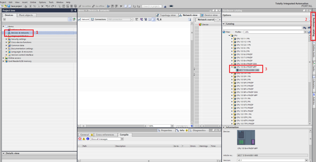
    1. Add a CPU to Your Project

    Start by opening the Device & Networks view. On the left side, you’ll find the Hardware Catalog. From here, locate the exact model of your CPU. Once you find it, drag and drop it into the main area (the device view) to add it to your project.

    Adding CPU to Project

    2. Configure PLC Security Settings

    Here, you can choose to set a password for your PLC if desired. This adds a layer of protection to your hardware configuration.

    PLC Security Settings

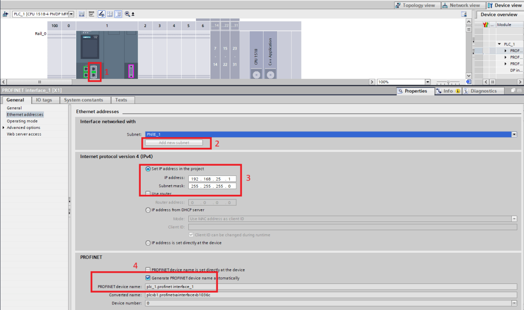
    3. Assign Network Settings
    Next, you’ll need to configure the network settings for the CPU:

    • IP Address
    • Subnet Mask
    • PROFINET Device Name

    These settings are essential for communication with your PC and other networked devices.

    Assign Network Settigns

    4. Access Control Settings
    Once your CPU is added and configured, select it in the Device & Networks view and navigate to the “Access Protection” section

    Here, you can choose whether to disable access control or set up user-based access depending on your project requirements

    5. Compile Your Project
    Before downloading, it’s important to compile the hardware configuration to check for any errors:

    • Go to “Compile” and choose “Hardware (Rebuild All)”.

    If the compilation is successful, you’re ready to download the configuration to the PLC.

    Compile project

    6. Download to the PLC
    Connect to your PLC via the appropriate interface (e.g., Ethernet).

    Click “Download to Device”, follow the steps to select your interface and transfer the configuration.

    Downlod Project

    7. Go Online
    Once the download is complete, click “Go Online” to connect your project with the physical CPU.
    You can now monitor, test, and debug your program in real time.

    Go Online Button

    Online View

    8. Start or Stop the CPU

    After going online, you can control the CPU operating mode directly from TIA Portal.
    To start or stop the CPU

    • At the top of the interface, in the “Online” tab, you’ll find the Start/Stop CPU controls.
    • This section shows the current operating state of the CPU (e.g. RUN, STOP), and allows you to:
      • Start the CPU (RUN mode)
      • Stop the CPU (STOP mode)

    💡It’s a good practice to set the CPU to “Stop” before downloading hardware or software changes, and then restart it once everything is updated.

    Important Note: Hardware Switch Overrides

    Some PLC CPUs have a physical RUN/STOP switch.

    If this switch is set to STOP, the CPU will remain in STOP mode, even if you try to start it from TIA Portal.

    ⚠️ The physical switch always takes priority over the software commands.

    Make sure the switch is set to RUN or RUN-P (if available) to allow software control.

    Stop / Start CPU from TIA portal

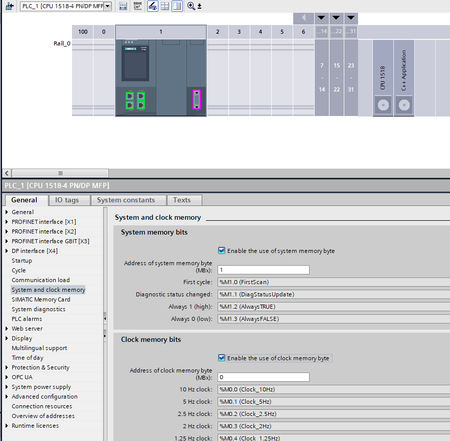
    Enabling System Memory & Clock Memory Bits

    As an optional but very useful step, you can enable System Memory bits and Clock Memory bits in the CPU configuration:

    1. Select the CPU in your hardware view.
    2. In the Properties pane, go to “System and Clock Memory” (or similarly named setting).
    3. Tick (enable) the following options:
      • Enable the use of system memory byte
      • Enable the use of clock memory byte

    By doing so:

    • The system memory byte provides a few built‑in bits for common internal functions (e.g. first scan flag, diagnostic status changes, always‑1, always‑0).
    • The clock memory byte divides that byte into 8 bits, each of which toggles automatically at a fixed frequency (from 0.5 Hz up to 10 Hz), useful for blinking signals, time‑based events, etc.

    Keep in mind: you must choose a memory byte (MBx) address for those bits that does not conflict with your other M memory usage.


    If you found this helpful, please consider supporting with a small donation. Thank you!

  • PLC Steps

    Simplify, Learn, Automate

    Γνῶσις δύναμις ἐστίν

    What is TIA Portal?

    The Totally Integrated Automation Portal (TIA Portal) by Siemens is an engineering software used for programming, configuring, and commissioning automation devices such as PLCs, HMIs, and drives. It provides a unified environment that allows users to develop and manage automation projects efficiently.

    Whether you’re working on a small machine or a complex industrial system, TIA Portal helps streamline the process—from hardware configuration to software development and diagnostics.

    Tia portal Icon

    Changing the IP Address of the Computer

    To establish communication between your PC and the PLC (CPU), both devices must be on the same IP subnet. This ensures that they can “see” each other over the network. In most cases, especially during initial setup or testing, it’s best to assign a static IP address to your PC.

    You can configure the static IP via the Network Adapter Settings in Windows. Choose the Ethernet adapter you’ll use to connect to the PLC, and set an IP address that matches the PLC’s subnet (e.g., if the PLC is 192.168.1.1, you can assign 192.168.1.198 to the PC, with subnet mask 255.255.255.0).

    Changing IP address of the Computer

    Changing the IP Address of the CPU

    There are two main ways to change the IP address of a Siemens CPU (PLC)
    1. Directly from the device screen (if available)

    • If your CPU or HMI panel includes a display, you can navigate through its menu to configure the IP address manually. This is useful for quick changes without a PC connection.

    2. Via TIA Portal:

    • You can also assign an IP address through TIA Portal. Open an existing project or create a new one. In the project view, go to the Online access tab (bottom-left corner), select the correct network interface (e.g., your Ethernet adapter), and click Update accessible devices”. Once the CPU is detected, right-click on it and choose Online & Diagnostics.
    • From the diagnostics panel, go to Functions → Assign IP Address. Here you can set both the IP address and the PROFINET device name.

    ⚠️ Important: If you’re using an existing project, make sure to retrieve the correct PROFINET device name from the Device & Networks section. Since the communication uses the PROFINET protocol, both the IP address and the device name must match exactly for successful connection and project download.

    Changing IP address of the CPU


    If you found this helpful, please consider supporting with a small donation. Thank you!